NIXIE CLOCK DIY
You can find the password of PDF inside the KIT BOX.
Please use Acrobat Reader from ADOBE to open the PDF in the page,or you may not be able to get the attached files inside the PDF if using other PDF reader!!!
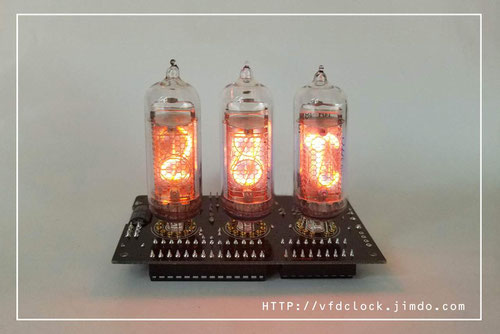
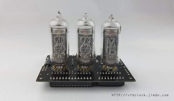
USB Powered NIXIE Thermometer-DIP version-IN-14+IN-19
Fully Open Hardware, Fully Open source, Arduino C code
This is my first USB Powered NIXIE Thermometer design,the prototype has been working for about half year, works great.
We use Atmega328 MCU and DS18B20 sensor in this design.
Features(for reference only):
1.Fully open hardware+Fully open source code(ARDUNIO Source code in pure C);
2.Fully DIP components ,easy to assemble;
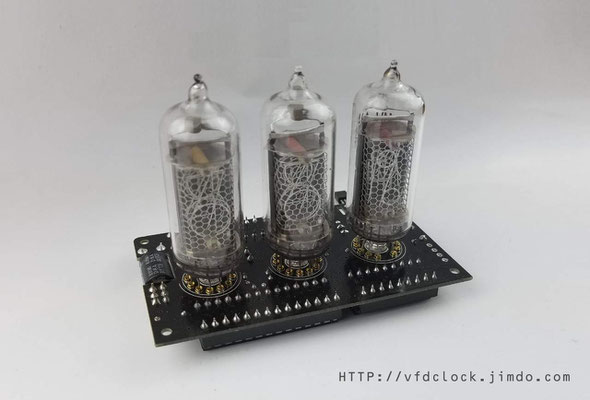
3.You can solder the NIXIE tube on the PCB directly or update to the plug-able version which you can just solder the female socket pins on the PCB first then
Plug the NIXIE tubes on it by hand;
4.USB Powered, almost no heat when working;
5.All 0~9 segs in 2 IN-14 tubes can be light up, and all segs in the IN-19 tubes can be light up too;
6.Pure C Arduino source code, easy to understand, you can change the code by yourself or port to other platform if you wanna;
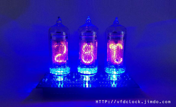
7.It has leds under 3 NIXIE tubes, light it up or not depends on your own code;
USB Powered
IN-14 + IN-19 NIXIE thermometer for ARDUINO
Assembly Instructions
V1.0
Notice
For assembling the NIXIE thermometer you need to have the skill of soldering DIP components. We use a Hakko FX-888 Soldering Station (with CF2 Iron Head). We use 183℃(degree C)low melt temperature solder wire S60, 0.5mm(Dia.), Brand Almit.
For how to solder the DIP components, we recommend:
https://www.hakko.com/english/tip_selection/type_bc_c.html
https://www.hakkousa.com/video/
Please do not change any equipments of the KIT or you may not be able to get the KIT in
working.
Because it contains no SMD components, so it is very easy for you to assemble, we recommend to check the circuit diagram carefully and follow the steps shown blow.
We do not recommend you to solder the components in random order or if it has problems you will need more time for de-soldering(*Will damage the PCB Pad) and debug, we recommend you follow the steps in this instructions that you can do part test after finished each step.
For more info & update, please visit HTTP://vfdclock.jimdo.com
Or contact us: [email protected]
Thanks for choosing our product.
Building it
Well, because of the circuit is block based and not very complicated, all you need to do is get all the components in the right position and make sure no short or no float before you plug the power in. We will show the soldering steps blow.
Preparing
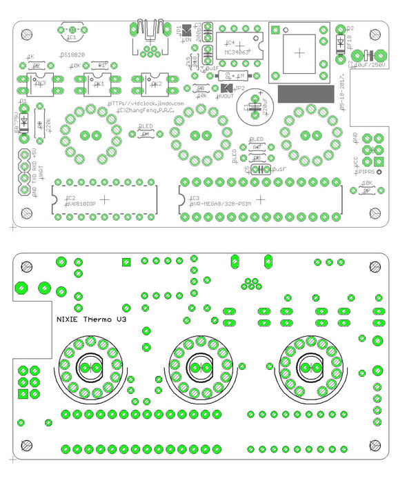
1. Please print out the PCB installation diagram by yourself, the Circuit diagram is no need for soldering job, print it or not depends on you(Note: May only have the paper circuit diagram in the KIT with no digital version provide.);
2. Check all the components in the kit bag, make sure nothing is missing (You can do this on a A4 white copy paper);
3. We recommend using a soldering station and small soldering tip for soldering this kit (we use F2 or CF2 type tip). We recommend using ~180℃ type soldering tin for this job. Please do not use the high temperature soldering tin in this project or you will damage components or the PCB;
Step 1: Solder the Electronic PINs for NIXIE
(*If not the plug-able version, please skip this step)
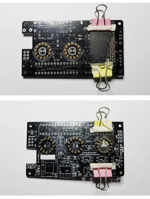
For the Plug-able version, please solder the PINS in the first place. You can plug the PINs on the top
of the PCB then cover a had board like a small PCB or small wood board over the PINs, use two clamps to hold it with the main PCB, then flip the PCB. Now you can solder on the other side.
Tips: Because of the PINs are through hole version, please solder it carefully and do not let the tin goes in to the inside of the pins or will damage the PINs.
If necessary, you can plug a wood /bamboo toothpick in the PINs hole when soldering.
Step 2: USB Power In and HV part
Solder the [USB Power In] part next; This part contains a USB socket and Boost circuit.
For soldering the USB socket, we recommend solder the middle Pins first, then flip the PCB to the other side solder the two fixed side legs.
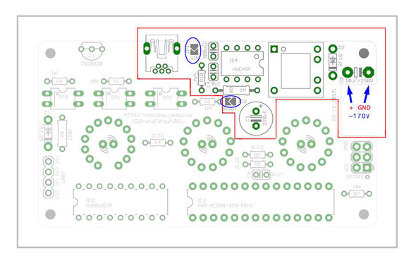
Then solder the Boost circuit part, it contains a DIP8 chip (We recommend solder it directly on PCB, do not use Chip Socket, because of if the Chip pins do not touch very well in the socket,the HV output may lost control).
Other Resistors and Capacitors are easy cake, for the diode, please check the direction carefully, the cathode side contains a black or white mark.
Also take care of the C1 and C2(Aluminum Electrolytic Capacitor), it has polarity, do not install it in
invert direction;
Especially for Aluminum Electrolytic Capacitor cap,usually it contains a white(or other
color long brand to mark the NEG(GND) pin on it's surface),this NEG(GND) pin needs to be plugged in the full-filled squire side of the mark on the PCB cap mark!!! Thus IN this case,C2 white marked side should be installed on the out-edge side of the PCB!
This part of the circuit contains two Jumpers ,JP1 for 5Vin, and JP2 for HV output, remember to solder these two jumpers close. We designed these two jumpers for easy to separate the HV part circuit from other circuits, easy for debugging;
After soldering all components(* Do not go power on if only solder part of the components of this circuit or the HV output will lost control and damage components!!!) in these circuit, and double check it, then you can plug the USB 5V in. If the circuit in working, you can find about 170V output in the two side of the C2 capacitor;

Step 3: HV lift part
In this step, you only need to solder one resistor and one diode, usually the diode is the small glass one, the cathode side contains a black or others color mark, please do not go invert.
(*Please note that the value of the resistor in this part is:
220K if using the HV6810 Chip in KIT;
100K if using the ST6810/16810 Chip in KIT;
And please use 1W resistor if you damaged the org one).
After soldering this part, you can measure the voltage of this part, it will have about 50V~75V range voltage between the glass diode;

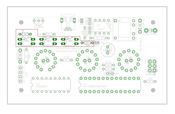
Step 4: OP(optocoupler) Driver part
Now we can solder the OP driver part components. This part of the circuit contains 2pcs resistors (1k and 10k), and 3pcs of OP(optocoupler), just need to take care of the OP direction, do not go invert;
And because of the circuit connected to the High Voltage circuit, the 10K resistor in this part you need to use the big one(1/2w) resistor, do not use the small (1/6W or 1/8W) one, or the resistor will be damaged under high voltage and the circuit will not work stable;
Step 5: Chips part
The Chips part contains 2pcs DIP chips + 1pcs DS18B20 sensor chip and 2 resistors and 1 capacitor;
The 2 DIP chips can be installed directly or installed by using the DIP socket(*May need to prepare the chip sockets by yourself!!!) depends on you. Please take care of the Chips direction;
Tips: For the DS18B20 sensor we recommend you keep the legs uncut and after soldering it on the PCB, you can band it into 90 degree position;

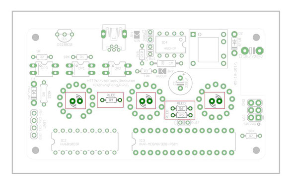
Step 6: LED part
The LED part contains 3pcs LEDs and 3pcs resistors; please note that the LED should be installed on the
top side of the PCB, and please solder the LED fast to prevent its be damaged;
The Led resistors may have different value for RED LED or Blue LED or others color LED, the RLED will be stored with the LEDs, usually the value is in 150R~330R range.
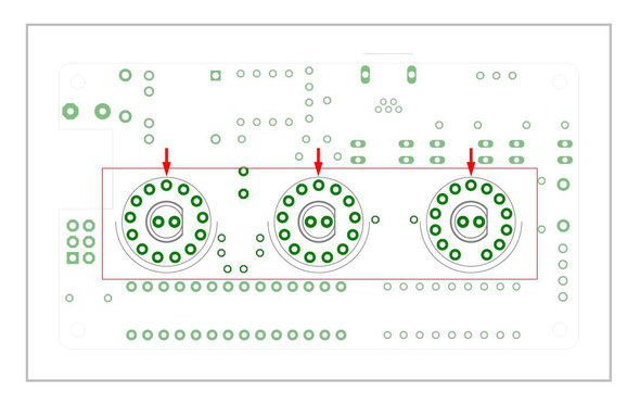
Step 7: NIXIE tubes part
For none plug-able version, you do need to solder the NIXIE tubes on the PCB; Before you solder the NIXIE tubes on, we recommend you test the LEDs first to see if it works fine.
In soldering the NIXIE tubes, we recommend you solder one or two legs of tube first, then you can adjust the tubes location ,make sure the tube has been installed vertically then you can solder the rest legs;
And please note the IN-14 tubes' anode pin should be plugged to the back middle hole as shown in the picture, usually for the IN-14&IN-19 NIXIE tube, the part of anode pin inside the NIXIE tube contains a white socket, easy to find out, and for IN-19 NIXIE tube, you will also find a short legs in front of the tube which is useless, you need to cut it off before you solder the tube on the PCB. And for IN-19 tube, you also need to expands the legs a little bit wide for easy to plug it in the PCB;
For plug-able version, you can just cut the legs in about 1cm length, then you can plug the tube in the socket which has been installed in the 1st step. For IN-19 tube, also need to cut the front short leg and expand all of the rest legs a little bit for easy to plug in; We recommend using sharp scissors to cut the legs into 45 degree sharp end, that will be easy for you to plug the tubes in the socket;
Step 7: First Testing
After finished all the steps shown up, please recheck it to see if has no error on PCB.
Now we can plug the USB power in, if all fine, the NIXIE tubes will display the temperature after self testing.
If has error, or the PCB did not work, please recheck the circuit block by block to see if it has any shot or float on PCB.

Step 8: Cleaning Circuit Board
You can use the household rubbing alcohol and a toothbrush to remove the solder flux on the PCB.
If available, the anhydrous alcohol (used for electronics cleaning) works much faster. Blot the cleaned area with a non-linting tissue (like Kimwipes EX-L) or a clean towel or you can do it in your own way.
update code
Step 9: Extras
There are UART and AVR SPI port has been designed on PCb, if you need to use these functions, solder PINs by yourself.(*Prepare STD. 1*4 PINs(UART) and(or) 2*3 Pins(SPI) by yourself.)
Add-ons: