 NIXIE CLOCK DIY

VFD48 MINI
Pure C source code for Arduino V1.0.4
Please use ACROBAT READER to open it or you may not be able to get the attach file inside it.
Please select ARDUINO UNO board in arduino compiler.
if can not open pdf attached file,would please send us a email,we will send u src directly,u can gind our email address inside pdf file.
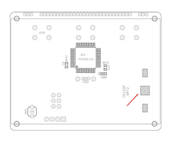
First,solder the front side of PCB, It contains few equipments on this side,please double check the direction of the PT6315 Chip before soldering it on PCB.
Recommend glue the chip on PCB by using tape before soldering.
Remember tin the middle pad of the CR1220 battery socket,and check the direction of the battery socket.
Plug the CDS sensor near the PCB or it will effect the VFD48 panel installtion.

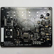
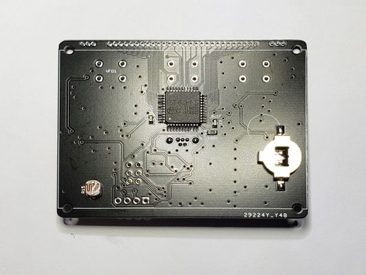
Most of the equipment on the back side of the PCB,please solder it carefully.
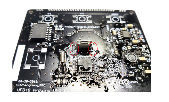
1)Solder the MCU part first and the crystal part,please double check the direction of MCU and solder the crystal fast,other small resistors and caps are easy.
2)solder the -HV part on the right bottom side and filament driver part on the top bottom side,same as the prv. step,please double check the IC direction and solder fast.


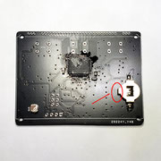
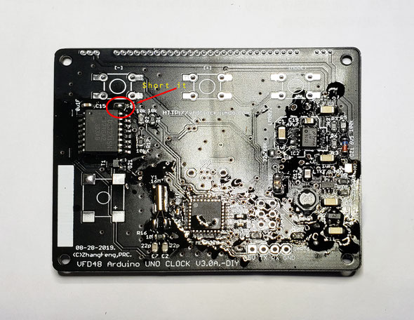
3)Solder the RTC part on the top-right side of the PCB,in this part,remember to short the small pad on the top of the RTC chip, this pad is for the 5V supply of the RTC chip, if you left it open, the RTC chip will not work.
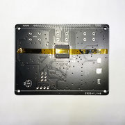
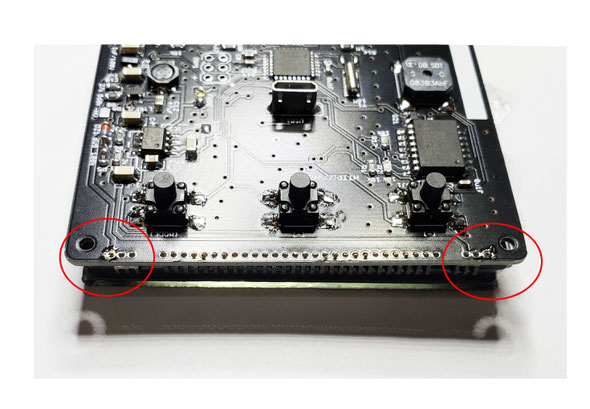
4) Solder the USB socket on PCB,please also remember to solder the left and right holes part of the usb soket as shown on the pic.
Give it a double check of all the components, if all fine ,we can do a test to see if the PCB in working.
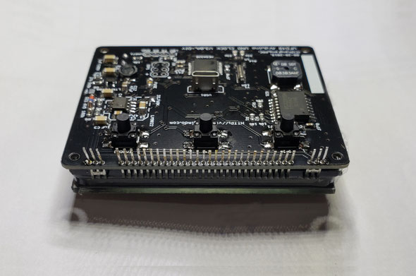
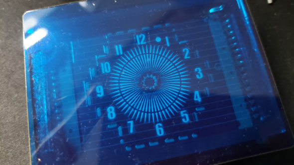
We plug the VFD48 panel on the PCB,press it to make all its legs touchs the holes, then plug the USB power on,if all fine,the VFD48 panel will in running. It will be light up,and the time will ticking.
!!!Do not solder the VFD48 panel on if the circuit did not work!!!
If all fine,you can wash the PCB to make it clean.

Then we will solder the rest components on the PCB.The keys and buzzer can not be washed,thus we nned to solder these things in the last step.
5) cut the keys' legs short then plug it on the PCB,you can solder it on the top or on the bottom side of the PCB.

6)Solder the buzzer on the PCB,please double check it's direction,check the [+] pad.

7) Plug the VFD48 panel on the PCB,power on ,recheck all things again,if all fine,you can solder the VFD48 panel on.
Tips:you can older the left one leg first then adjust the installtuon height of the panel,then solder the one leg of the left side. if all fine,then you can sut all the legs short,solder all the rest legs on the PCB.
After assemble the PCB,we recommend you do at least 48Hours heat testing,if all fine,then we can install it in the aluminum enclosure.

Aluminum Enclosure Assembly Instructions

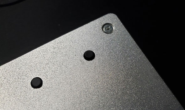
First install the 5mm Copper column as shown in the pic.
Then glue the blue filter on the VFD48 panel by using double-side tape.Recommend glue on the top and bottom side.
The blue filter contains protective film on both side,remove it before you use it.
Now install the PCB into the aluminum enclosure. Then glue the front panel on by using the double-side tape on its surface.
Done!
