NIXIE CLOCK DIY
In this article we are going to teach you how to create a fast tesing PCB if u have a CO2 laser cut.
For small size testing PCB,it costs us less than 30 mins to get a working PCB.
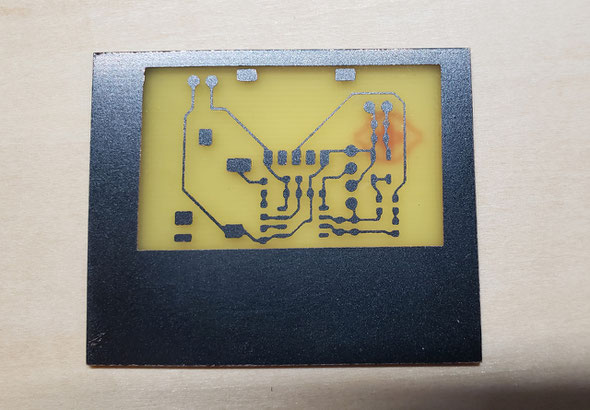
First prepare a regulaer PCB made by factory with a clean area that contains flat copper under the Green UV painting as u can see in the pic.
In this sample,we use an old Li-ion battery PCB which we designed for installing battery for our IN-18 SD clock PRO. It contains enough space to create our testing PCB.
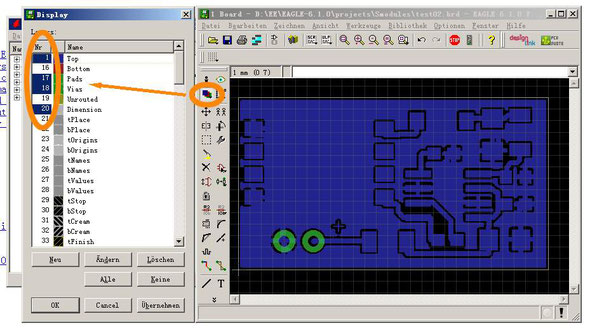
We are using EAGLE PCB V6 software, now export the first mask picture.
As u can see in the TOP pic,first,display only [TOP]+[PADS]+[Vias]+[Dimention] layers only.

Then export the first mask pic to a BMP file,by using export -> image function as u can see in the picture.
We use 1200dpi high resolution and output [Monochrome] BMP file.
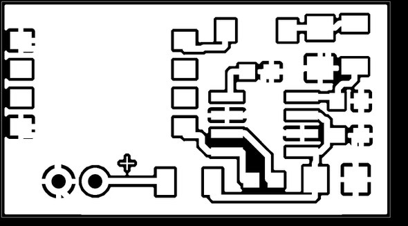
Here is the output a.bmp mask file. Then import the BMP file to ur Laser Cut Software to burn it to the PCB.
We are using a 40W 3040 Co2 laser cut machine,only need to set 7%~10% output laser power, this power is enough to burn the green UV painting layer from the PCB surface.
After washing the PCB surface,we can goto the etching PCB part.

In eaching part,u can use:
1. Use traditonal FeCl3(direty);
2. Use mixture of hydrogen peroxide (H2O2) and hydrochloric acid (HCl) in about water+H2O2+HCl=1:1:1 ratio; (Fast,but damgerous);
3. Use Sodium persulfate (Na2S2O8);(the key is the temperature and pumping air bulb in);
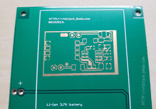
After the PCB is being etched,need to remove the green UV painting on its surface.if u do not need any of the green painting on it,u can use sandpaper to remove all of it. But we can do it in more elegant way as u can see later.

Let us output another mask that contains the [Pads]+[Dimention]+[tCream] layers.
The problem in this step is the cream parts are not displayed in solid color,we need to change the layer setting to make it displays in solid way.

Double click the bar near "31[ ]tCream" in the layers list,change it to solid color.As u can see in the picture,no need to care about the color because we will output the mask into mono in the next step.

Do the same step to export it to a BMP file in 1200dpi, monochrome as u have done before.

Here is the output b.bmp mask file. Then import the BMP file to ur Laser Cut Software to burn it to the PCB.
Then all the parts that need to be solder will be appeared without green painting.
TIPS:
If need to drill holes,we recommend u do it before etching.
If need to get more HQ result,do Co2 laser focus calibration first;
If u want to output the PADs in Solid with no middle hole,please change the setting shows in blow picture.
Coating a layer of black painting on regular cu PCB surface also works fine.Pics shown blow.