 NIXIE CLOCK DIY

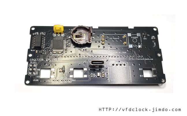
1. It is recommended to start the welding work from the front first. The first part to be welded is the PT6513 driver IC. Use tape to temporarily fix the IC on the PCB and align the pins of the
IC. Please pay special attention to the direction of the first pin and do not mess with it. wrong;
Then apply flux on the pins and use a soldering iron to solder; use a magnifying glass to inspect after the soldering is completed to ensure that the pins are soldered correctly and there are no
false soldering or short circuits;
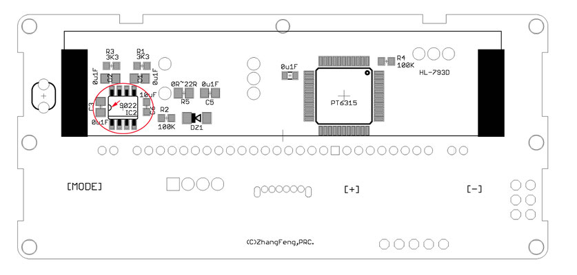
2. Solder the LM9022/AP9022 integrated circuit using the same method, also paying attention to the direction of the IC;


3. When welding the resistors, capacitors, diodes and other parts on the front, please pay attention to the correct placement direction of the diodes;

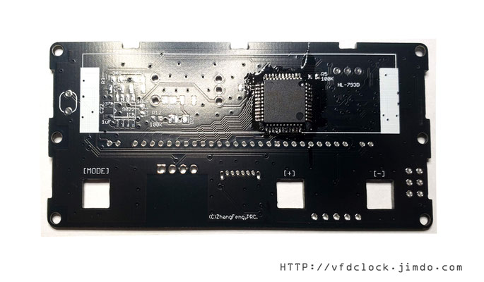
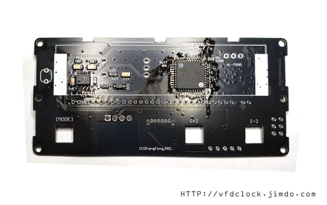
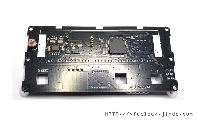
4. Turn the PCB over to the reverse side and use the same technique to solder the MCU Mega328 and RTC RX8025T, as well as other RCL and other parts; C23 and D4 on the lower left side are optional parts and are only used for the online UART programming port. If not needed Modify the program without welding;

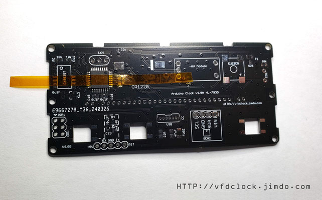


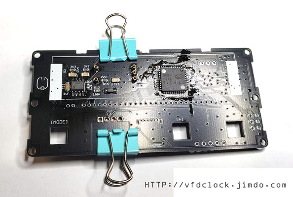
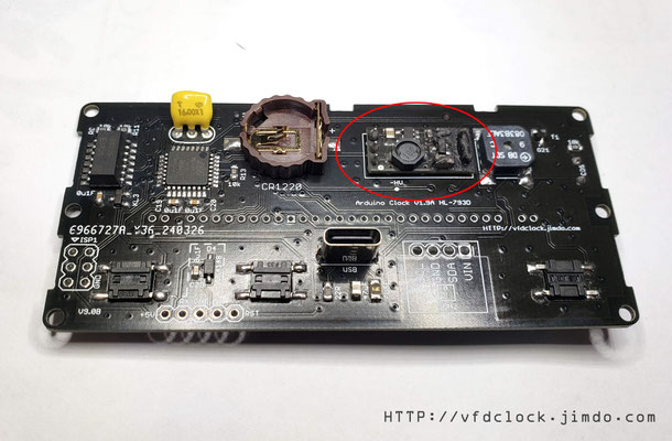
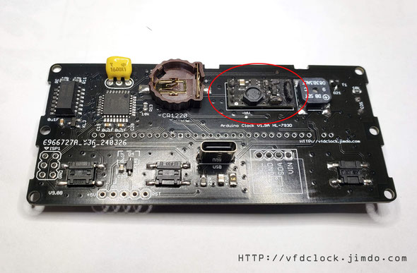
5. Then solder the female pin part used by the HV power module. First insert the female pin into the PCB, then cover it with a hard board, you can use PCB or wood chips, use clips on both sides to clamp the PCB, then flip the PCB over and solder the lower part;


6. Weld the 16M crystal (the pins have no directionality), CR1220 battery holder (please pay attention to the installation direction) and CDS photosensitive sensor (it is recommended that the installation height does not exceed the height of the VFD screen);

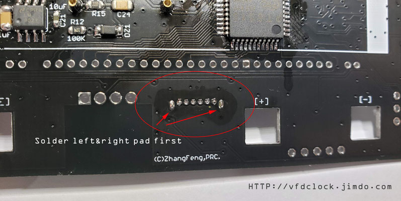
7. Solder the USB socket. First, insert the USB socket into the PCB. There is only one direction for insertion (as shown in the picture). Then flip the PCB and solder the left and right mounting pins first. After confirming that the USB position is correct and the installation is not skewed, you can solder the other ones. Pin; after the soldering is completed, flip the PCB over and add solder to the left and right lower sides of the USB socket to make it secure;


8. After the above welding work is completed, you can use alcohol and other cleaning agents to clean the PCB; because the RTC contains crystals, ultrasonic cleaning machines are not allowed!
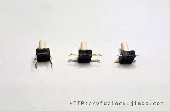
9. Then weld the buttons and other parts. First, unfold the four legs of the button, flatten them with a tool, cut them short, and then insert them into the PCB mounting holes for soldering. The buttons have two specifications, the taller one is used for the [mode] button, and the two shorter ones are used for the [+] and [-] buttons; after the button welding is completed, the speaker can be welded (please pay attention to the "+" pin direction). After completion, the -HV power module can be inserted;
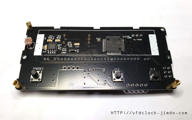
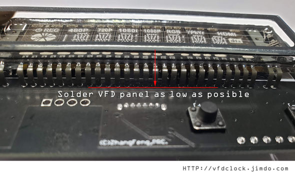
10. Install VFD screen. Before installing the screen, please confirm that the circuit board is working correctly. First insert the VFD screen into the circuit board, then apply force on one side to press the pins against the inner wall of the installation hole, and then plug it in for testing. If the VFD screen lights up correctly and displays normally , the pins can be soldered, otherwise the PCB fault needs to be eliminated before proceeding to the next step. When welding, make sure the screen pins are pressed as low as possible and as close to the PCB as possible (as shown in the picture), otherwise it may not be installed into the housing later;


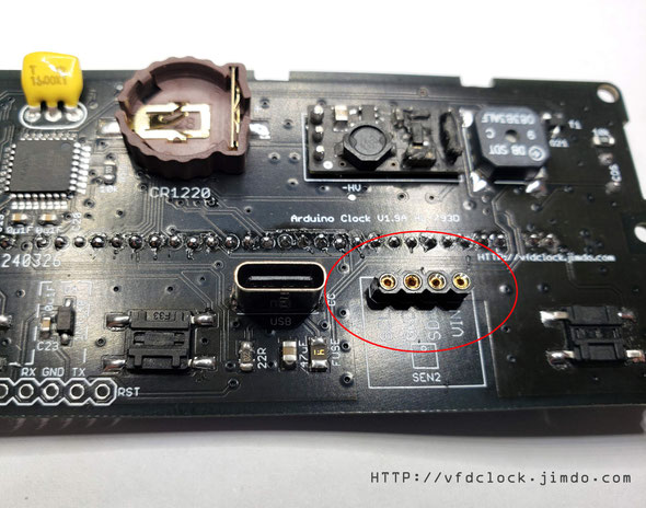
12. Additional functions: If the clock is equipped with a temperature and humidity display function, you need to weld an installation socket for the temperature and humidity sensor, and directly weld the 5pin female socket to the corresponding position.
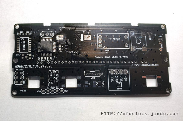
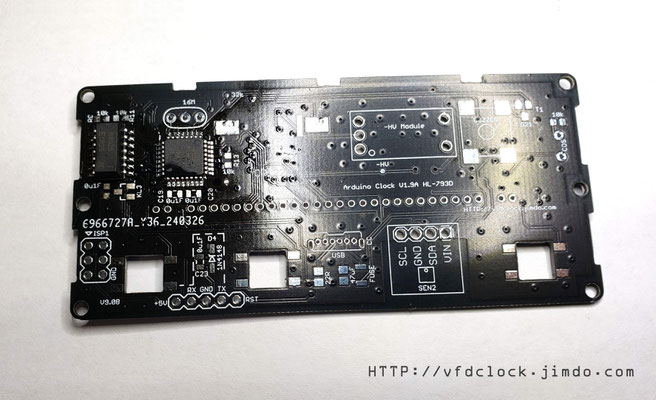
Top and Bottom sides of PCB

Enclosure assembly instructions
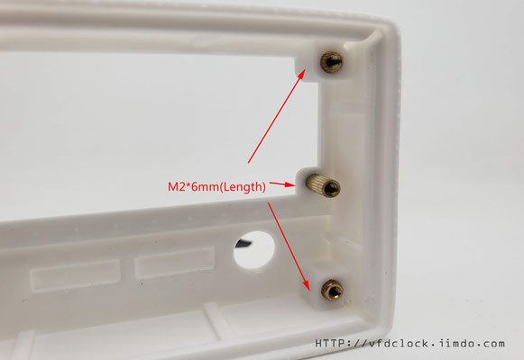
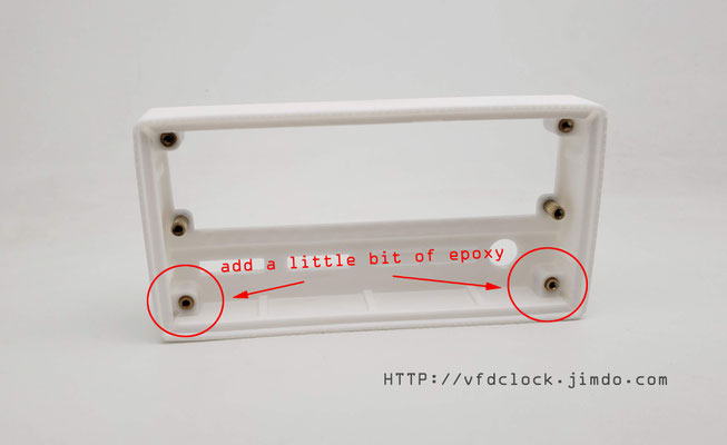
1. First install 6 M2*6mm (length) copper pillars inside the casing. The bottom two need to be bonded into the mounting holes with a small amount of epoxy resin. The remaining four are used on
the front panel of the casing. Screws for fixation;


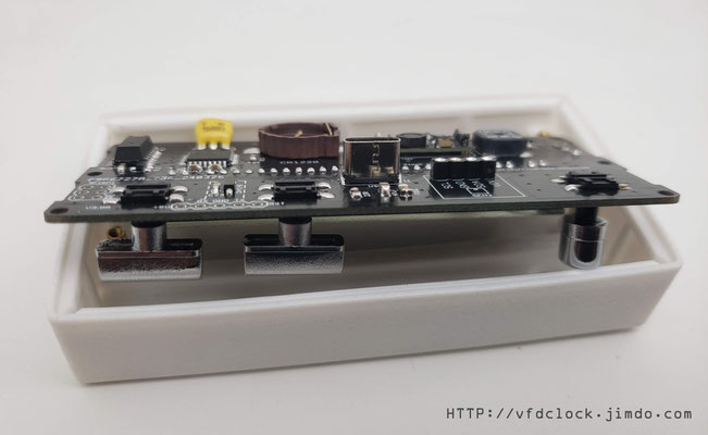
2. Install the key cap on the key, press the key head firmly (please pay special attention to using your fingers or other things to support the bottom of the key when pressing to prevent it from falling off the PCB), and adjust the approximate position of the key cap. Then tilt the PCB into the case until it is in place. Please pay special attention to the fact that the key cap needs to be exposed from the front mounting hole; (Tip: If necessary, consider using a small amount of epoxy resin on the back of the PCB to stick the keys to the PCB. Prevent the button from detaching from the PCB due to excessive pressing force that may occur during use);


3. We recommend first using foam double-sided tape to stick the VFD screen to the PCB, then put the circuit board into the housing and place it in a good position, and then install the fixing copper pillars (M2*5mm ( Body length) + 3mm (screw length)) and screws. It is recommended to use tweezers to clamp the inner hole of the copper pillar for rotational installation;

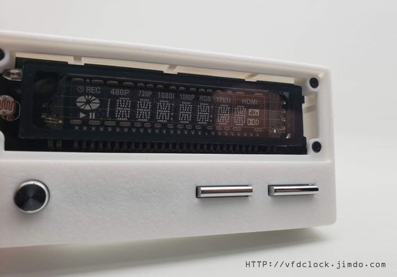
4. Install the front panel. First remove the protective film on the front panel. The protective film may have multiple layers. The last protective film on the front can be left until the final installation is completed and then removed. Use double-sided tape to install the front panel in place. Depending on the version Different, the front panel may have up and down installation directions, please pay attention;


5. The last step is to install the back panel. This part is relatively simple. You only need to remove the protective film of the back panel and then use screws to fix it in place;


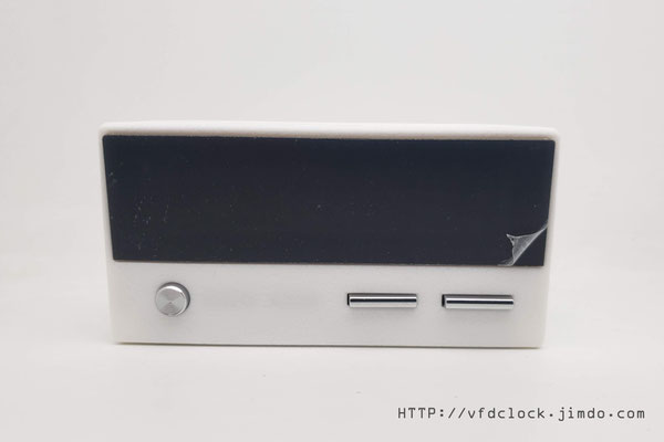
6.Here is the final fully assembled VFD clock.

User Application Instructions
In editing...
