 NIXIE CLOCK DIY
5V USB Powered-IN-18 6-tube Clock DIY version
Assembly Instructions
V1.0
Notice
For assembling this NIXIE KIT you need to have the skill of soldering DIP& SMD components. We use a Hakko FX-888 Soldering Station (with CF2 Iron Head). We use 183℃(degree C)low melt
temperature solder wire S60, 0.5mm(Dia.), Brand Almit.And for most of the SMD components are big size and easy to be assembled,if you have a Hot air blower station,will help.
For how to solder the DIP components, we recommend:
https://www.hakko.com/english/tip_selection/type_bc_c.html
https://www.hakkousa.com/video/
For how to solder the SMD components, we recommend:
https://www.hakko.com/english/tip_selection/type_bc_c.html
https://www.hakkousa.com/video/
Please do not change any equipments of the KIT or you may not be able to get the KIT in working.
Because it most of SMD components are big size, so it is very easy for you to assemble, we recommend to check the circuit diagram carefully and follow the steps shown blow.
We do not recommend you to solder the components in random order or if it has problems you will need more time for de-soldering(*Will damage the PCB Pad) and debug, we recommend you follow the steps in this instructions that you can do part test after finished each step.
For more info & update, please visit HTTP://vfdclock.jimdo.com
Or contact us: [email protected]
Thanks for choosing our product.
Building it
Well, because of the circuit is block based and not very complicated, all you need to do is get all the components in the right position and make sure no short or no float before you plug
the power in. We will show the soldering steps blow.
Preparing
1. Please print out the PCB installation diagram by yourself, the Circuit diagram is no need for soldering job, print it or not depends on you(Note: May only have the paper circuit
diagram in the KIT with no digital version provide.);
2. Check all the components in the kit bag, make sure nothing is missing (You can do this on a A4 white copy paper);
3. We recommend using a soldering station and small soldering tip for soldering this kit (we use F2 or CF2 type tip). We recommend using ~180℃ type soldering tin for this job. Please do
not use the high temperature soldering tin in this project or you will damage components or the PCB;
Please always remember that in this new version,only LEDs and NIXIE PINS and comma PINs are installing on the TOP side of PCB,others are all on the bottom side of PCB.
And double check the component before you solder it on PCB, and also double check its' direction for some diode and caps etc.,DO not go wrong,because of if go wrong,de-soldering DIP components are not very easy, may damage the PCB pad.
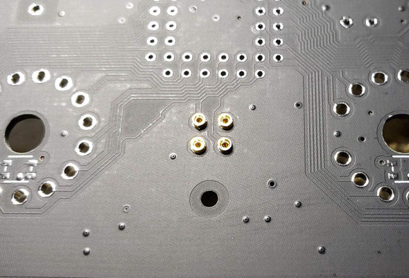
1): Middle comma Pins and HV module Pins
We need to solder some pins in this step,please solder it in this step,will be easier to be installed.
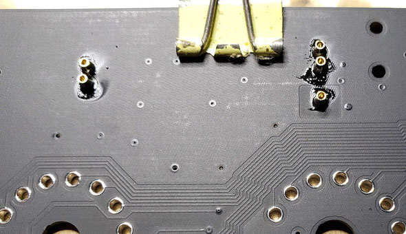
The first PINS are middle comma female pins,please plug the Female PINs on the top of the PCB then cover a had board like a small PCB or
small wood board etc.over the PINs, use two clamps to hold it with the main PCB, then flip the PCB. Now you can solder on the other side.
Tips: Because of the PINs are through hole version, please solder it carefully and do not let the tin goes in to the inside of the pins or will damage the PINs. If necessary, you can plug a
wood/bamboo toothpick in the bottom of PINs hole when soldering.
Test

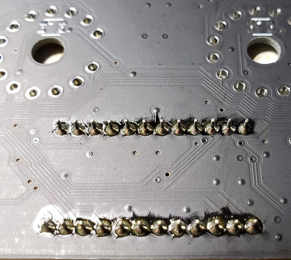
We have two types of HV moudles,for the SMD version ,you just need to solder it on the SMD PAD on the bottom side of PCB.
For the DIP version of HV moudle, we recommend you install it by using the female pins.
Please remember to install these pins on the bottom side of PCB,and use the same soldering methord same as the middle colon pins.

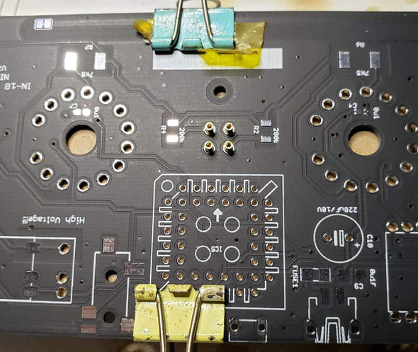
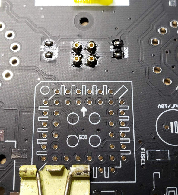
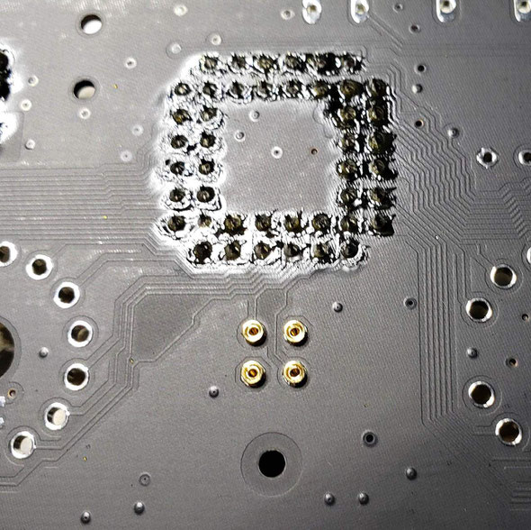
2): Middle comma Pins and MCU IC socket pins
Then solder the MCU IC sockt on the bottom of the PCB,this part is easy,just plug the IC socket in the PCB,flip it and press it on the table,then solder it. Please take care of the direction of the IC socket(check the first leg mark of the socket), do not go invert and do not go wrong PCB side.
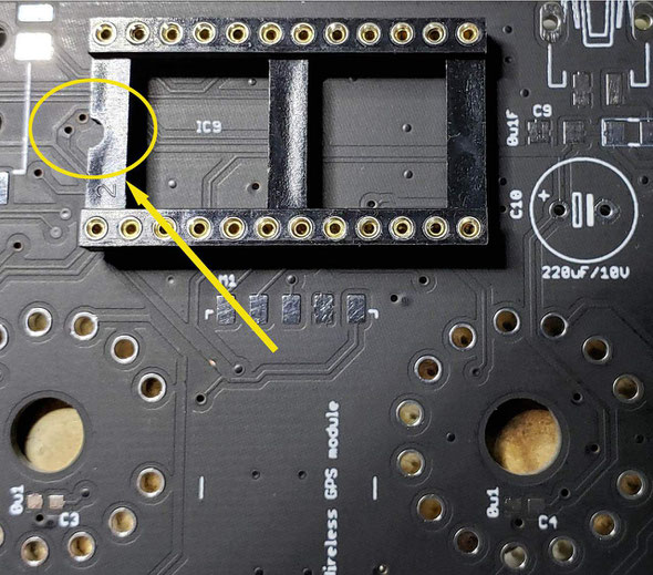
The PLCC44 SOCKETs, please take care of the first leg!!!
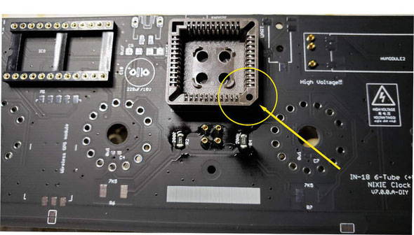
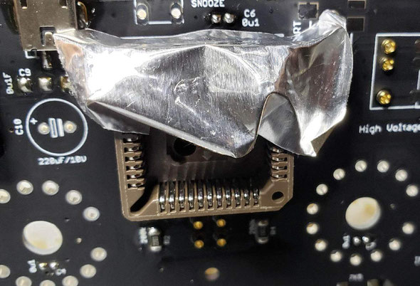
Tips: In order to protect the components like sockets, you can use aluminum foil to cover it's surface when you are using Hot air blower station to install the components near by.
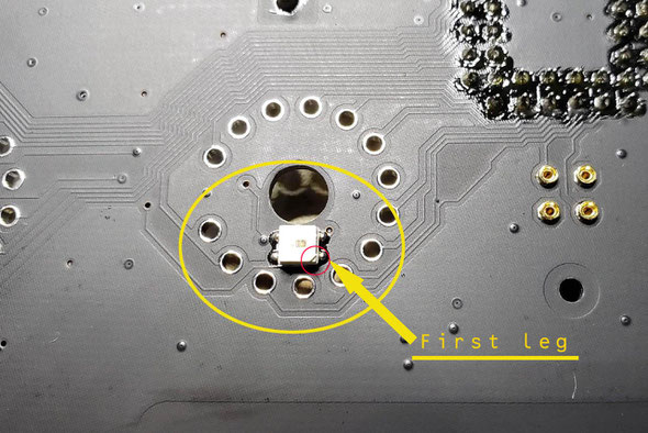
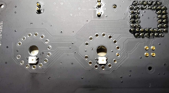
3): Install LEDs
The LED part contains 6pcs LEDs(With Chip inside it) and 6pcs 0uF(100nF) caps; Please note that the LED should be installed on the top side of the PCB, and take care of the first leg of the LED(The first leg is on the right-bottom side of LED with a tri. mark, and the LED pad has a white [.] to point out the first leg on PCB); Please solder the LED fast to prevent its be damaged;
Please solder the LEDs in low heat and solder it fast!!!
Do not forget to solder the 0u1(100nF) capacitor(s) near LEDs in this part on the bottom of PCB;

4): Install Main power and others components
The main power part has a USB socket(May in MINI USB/Micro USB),and a fuse, a 100nf cap and a Big Aluminum Electrolytic Capacitor(Please take care of it's direction).

Rest components are easy,please check the pic shown blow.
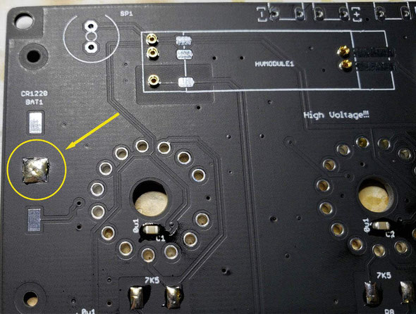
Notice:
For the CR1220 battery socket, please remember to tin the middle pad first and take care of the direction of the socket.

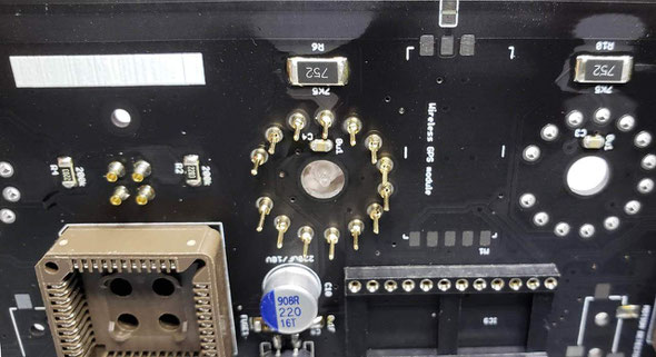
5): IN-18 PINS
Now we are going to solder the IN-18 PINS.Please flip the PCB to the front side,the PINS need to be installed on this side and please solder it on the middle part of the PINs;
First we recommend you plug the PINS in the IN-18 legs,then plug ALL the PINS to the install holds,plug it down to the middle part, then flip the PCB ,solder the PINs on the bottom side of PCB;
!!!Plase double check to see if all PINs are plugged to the middle part before you solder the PINs!!!

Plug down to the middle part of the PINS
Flip the PCB,then solder the PINS on the bottom side of PCB

In soldering the PINS,if necessary,you need to keep pushing the tubes down to make sure all the PINS have been soldered on the middle part, please trade care of this part.
!!!Pleas note, do not add too much tin in soldering PINs,and please solder it fast. If add to much tin, the tin may go inside of the PINs and will solder the IN-18 tube legs with the socket,which will be big problem. We recommend add a little bit body lotion or oil on the surface of all in-18 PINs, will help to prevent be soldered together with socket.

And after finished soldering on tube PINS,give it a power on test(*Remember to plug the MCU module and HV driver Chips and HV mpdules in socket for testing) to see if have any problem.
6): Power ON Test
After finished all the steps shown up, please recheck it to see if has errors on the PCB.
Then plug the two PLCC HV driver Chips and Main MCU module and HV modules in the sockets; please double check the direction of IC and module
before power on, do not go wrong direction.
Now we can plug the 5V(At least 1A5) power in, if all fine, the NIXIE tubes will display the time.We recommend plug one NIXIE tube in when in the first time power on test, if first NIXIE tube
works, you can go power off and add another one, do test again...etc., until all 6 tubes are all in working;
If find errors or the the clock did not work, please go power off and re-check the circuit block by block to see if it has any short or float on PCB;
Step (8): Cleaning the Circuit Board
You can use the household rubbing alcohol and a toothbrush to remove the solder flux on the PCB.
If available, the anhydrous alcohol (used for electronics cleaning) works much faster. Blot the cleaned area with a non-linting tissue (like Kimwipes EX-L) or a clean towel or you can do it in your own way.
!!!Remember to remove the HV driver Chips and the MCU main board and hv modules(if in hv dip version) when cleaning the PCB!!!
You need to have a PLCC EXTRACTOR for unpluging the PLCC chip from the socket;
9): Buttons and Buzzer etc.
Because of Buttons and Buzzer etc. can not be washed, we need to solder 4pcs Keys and 1pcs Buzzer after cleaning the PCB.
If the Buttons are one side two pins version,just solder it directly on PCB,if the Buttons are two side 4pins version,cut one side 2 pins off buy yoursele,and band it flat the other side of 2pins then solder it and cut it short(or cut it short first before soldering);

It also has two 3.5mm plug socket,one is for GPS, the other is for "PIR Motion Sensor";Please remember to solder these on PCB too;
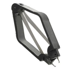
10): Create middle comma
For how to assembling the Middle comma,please visit:
KIT-Create the Middle Dot Comma for IN-18 NIXIE clock
You can make your own decision of the location of the bulbs in the middle glass tube.

Extras (10): misc extras
In editing...
